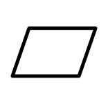
FLATNESS
GD&T Symbol: 
Relative to Datum: NO
MMC or LMC applicable: YES – ONLY TO FEATURE OF SIZE
Flatness is a Form type of Tolerance.

Relative to Datum: NO
MMC or LMC applicable: YES – ONLY TO FEATURE OF SIZE
Flatness is a Form type of Tolerance.
Flatness, As name suggests, this tolerance symbol controls how flat the surface is without any reference with datum or feature.
Flatness to the surface or feature ensure its condition of purely planer.
It is a 3D Tolerance zone (up and down variation) over the 2D flat plane.
MMC or LMC are applicable to only for feature of size and not to the surface.
Drawing Callout:
Feature control frame with flatness symbol can be indicated by leader arrow pointing to the surface or on the extension line drawn from the surface.Image : Drawing- Leader Option
Or, feature control frame can be connected to extension line,
Image : Drawing- Extension Line Option
Tolerance Zone:
Image: Pictorial Explanation of Flatness Tolerance
Above image gives the pictorial explanation of meaning of flatness tolerance
Entire referenced surface must lie between two sets of parallel planes show in blue color and 0.05 mm apart from each other as flatness tolerance value is 0.05.
Smaller the Tolerance zone, more Flatter the surface or feature.
The flatness tolerance value must be lesser than the size tolerance, when it is associated with the size tolerance.
Gauging and Measurement:
To measure the flatness height gauge is used, in modern days, CMM is the best option to use.
The height gauge or CMM run across the surface, to ensure the all the elements on the surface are within the tolerance zone, if not part can be rejected or can be go to discussion with designer.
Application:
Flatness is commonly used for the fixtures where the mating parts are to flushed. flatness also used for the plate on which other components assembled, so that relative function pf assembled parts should be maintained.


0 Comments