GD&T Symbols - Geometric Dimensions & Tolerance Symbols
GD&T stands for Geometric dimensions and Tolerances, It is symbolic
language used to define the nominal or allowable tolerances and variations in
models or drawings.
GD&T helps designers to say “what they mean?” with regard
to their design models or drawings.
ASME Y14.5 standard has standardized Geometric Dimension and
Tolerance symbols in detail.
Lets Learn about GD&T Symbols in this article.....
Note- To know the more about any symbol, Please click on the symbol name...
There are Five category of GD&T symbols that are used to define a
part design intent accurately. and these five symbols includes 14 GD&T
symbols that control part features and geometry.
Geometric Dimension and Control Tolerance
(GD&T) Symbols:
| SYMBOLS | GEOMETRIC CHARACTERISTICS |
 | STRAIGHTNESS |
 | FLATNESS |
 | CIRCULARITY (ROUNDNESS) |
 | CYLINDRICITY |
 | POSITION |
 | SYMMETRY |
 | CONCENTRICITY |
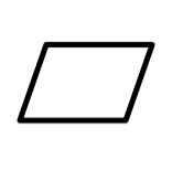
 | ANGULARITY |
 | PARALLELISM |
 | PERPENDICULARITY |
 | PROFILE OF A SURFACE |
 | PROFILE OF A LINE |
 | CIRCULAR RUNOUT |
 | TOTAL RUNOUT |


0 Comments